When I talk about names in this document I am referring to group names, and ONLY group names. Each plane and box must be placed in it's own group using the names described in this document. It is assumed that the reader knows how to do this in whatever modelling program they are using.
It is also assumed that the reader knows how to create a .E file for their mesh.
Additionally, this Document is primarily aimed at the creation of BIPED Meshes (i.e. people). However, much of this is still relevant for other types of meshes as well.
There are two ways to go about creating a custom mesh. There is the easy way and the hard way.
The easy way is pretty simple. Just download one of Shadowspawn's 3ds files that were converted from Thief1/2's RTG files. You can get them here (just scroll down a bit). Of course, only some of the Shadowspawn's files are actually BIPEDs. The 3ds files will have all of the correct group names for the rotation boxes and the limit planes. All that needs to be done is to delete the actual mesh and leave the rotation point boxes and the limit planes. You then create your own model around the planes and boxes. Once that is done convert, the mesh into a .E and then make the .BIN and .CAL (see the section "Making the .BIN and .CAL" for more info).
The hard way is of course to make your model, then place all the rotation point boxes and the limit planes yourself. Doing this takes a long time because each plane and boxes needs to in a group with the correct name. It is still a good idea to load up one of Shadowspawn's 3ds files to get an idea of the size of the model you'll need to use. As a guide, the units are the same as in Dromed, which means that one unit in the 3d modeller, is approx 1 Foot. Shadowspawn's 3ds files will also give an indication of the state the model should be in when modelling.
The joint system used in Mesh files consists of rotation boxes and limit planes. The planes are used to define volumes. There are two types of volumes, stretchy, which are the joints, and rigid, which are the bones. The rotation boxes define the point of rotation for each joint. The joints rotation box is also used as the position that Dromed and the Games use for placing objects on AIs.
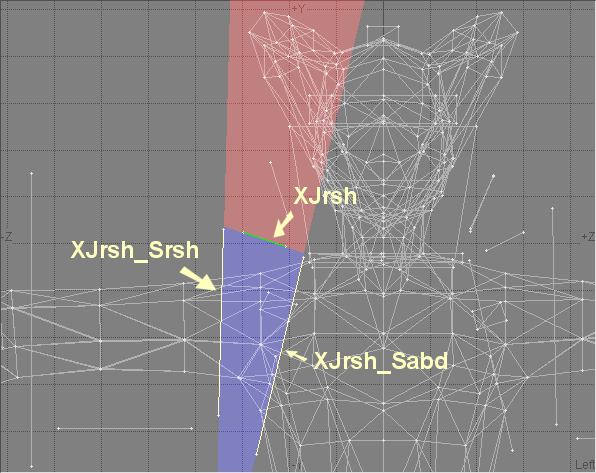
When making Meshes, some special precautions need to be taken because the joint and bone volumes will reach out to infinity. This can cause problems. Take the following image for example. In the image I've zoomed in on my Enforcer mesh and have highlighted some of the planes.
The planes named XJrsh, XJrsh_Sabd and XJrsh_Srsh make up the volume that is the right shoulder joint in the model. The blue shaded area is the actual volume. The red shaded area is what the volume would be if plane XJrsh was removed. As can be clearly seen, the shoulder joint volume would extend and start effecting the head of the model. This is obviously can not be allowed. This is something you will need to be aware of it when you make your model and when placing planes.
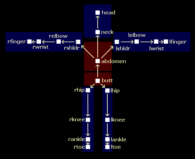
The names for the planes and boxes are derived from the MJO and MAP files that are passed to MESHBLD. The names used with a Mesh based on BIPED.MAP are ltoe, rtoe, lankle, rankle, lknee, rknee, lhip, rhip, butt, neck, lshldr, rshldr, lelbow, relbow, lwrist, rwrist, lfinger, rfinger, abdomen and head.
BIPED.MAP also contains numbers that are assigned to the joints. These numbers are referenced in the MJO file, which tells MESHBLD the connectivity of the torsos and limbs. The BIPEDNW.MJO file has 2 torsos and 5 limbs. The butt 'torso' is the base of the model. The leg limbs are connected to this 'torso'. The abdomen 'torso' is also connected to the butt. The arm limbs, and the neck/head limbs are connected to the abdomen. The following picture shows the connectivity between the joints. The areas shaded red are the torsos, and the areas shaded blue are limbs.
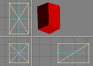
Naming the rotation box groups is really simple. They simply follow the pattern J****** where ****** is the name of a joint. An example name would be Jbutt that would be the box for the butt joint. It's that simple. The boxes should be constructed out of triangles that have their faces pointing in towards the center of box. As far as I can tell, orientation of the boxes doesn't matter much. The center of the box is used as the pivot point for the rotating joint. This picture shows one of the joint rotation boxes.
Naming the limit planes is a little more complex. As stated earlier, the planes are used to define to different types of volumes. To define the 2 types of volumes, there are 4 types of planes. The planes are made up of 2 triangles. Only the first 3 letters of the joint names are used when naming the planes. The naming conventions are as follows.
XJaaa_Saaa: Planes that use this naming convention are used to define the edge between a joint Jaaa and a bone Saaa. In this case both the volumes belong to the same joint aaa. The bone is a child of the joint. For instance a plane named XJrsh_Srsh is the edge between the right shoulder joint and the right shoulder 'bone' which is actually the upper arm. A plane with this name is pictured in one of the images above.
XJaaa_Sbbb: These are used to define the edge between a Bone Sbbb and a Joint Jaaa. In this case the joint volume is the child of the bone volume. An example a plane would be named XJrsh_Sabd. This plane would define the edge between the right shoulder joint and the abdomen 'bone'. This plane is also pictured above.
XJaaa and XSaaa: These are general limiting planes for volumes. They are used to stop the volume reaching out to infinity and effecting parts of they mesh they shouldn't. An example of a commonly used plane would be XJrsh that is used to stop the right shoulder volume effecting the head of a model. Again, pictured above.
XJaaa** and XSaaa**: These act exactly the same as XJaaa and XSaaa. The only difference is the **, that is a two digit number ranging from 01 to 99. The number is used so that more than one general limit plane can be used be volume. An example is XJrhi01 which, is a general limit plane that belongs to the right hip joint.
MESHBLD will ignore extra characters in a name if it detects them. However you must note that ignored characters are just that completely ignored. To MESHBLD the names XJrkn_Srkn#1 and XJrkn_Srkn#2 are both the same and mean XJrkn_Srkn. I strongly don't advise on adding extra characters to the end of plane names. There may be problems because some character may have special meaning that isn't yet known. In every case I've seen where the meshes have extra characters, there has always had a # so that may be used to define a comment. I don't know for sure, but it seems reasonable. Again, just don't do it, there is almost no reason to do it.
Here are some basic Rules:
1) All of the joints have a rigid and a stretchy volume, except for the base torso. The base Torso only has a rigid volume.
2) Volumes probably should not be placed for joints that don't actually exist.
3) The joints at the end of the limbs shouldn't be given any volumes. For a BIPED example, the head, rtoe, ltoe, rfinger and lfinger joints shouldn't have any volumes. The rotation box (which is placed) is used with Dromed for placing items in those positions.
4) No two planes can have the same name.
5) As far as I know, Volumes MUST be CONVEX. Concave volumes may not work as expected.
6) Volumes reach out to infinity if not edge capped with a general limit plane.
7) Make sure that you haven't made any typos in the plane and box names. If you have made a typo, things won't work. I learned this the hard way.
Here are some images of a Guard from Theif with the names of ths planes and boxes shown. It should give a good indication of how things work.
Image showing the plane group names of a Guard from Thief
Image showing the box group names of a Guard from Thief
Additionally, here are some images that show my Enforcer mesh with the planes and boxes named. It's a little bit different to the guard. I've also zoomed in on the head and abdomen region because the Enforcer has more planes there. Just one note, the XJnec_Snec plane is on an angle.
Image showing the Cyborg Enforcer Mesh with plane group names
Image showing the Cyborg Enforcer Mesh with box group names
Zoomed in area of the Cyborg Enforcer Mesh around the Head and Abdomen showing the names for the Planes and Boxed
Careful examination of the pictures of the Enforcer will reveal that there aren't any planes that define the volumes for the wrist joints and that the rigid elbow volumes are left open. This is intentional. I didn't put the volumes in because I didn't want the Enforcer to have wrist joints. I have still put the wrist rotational boxes though.
To make the .BIN and .CAL a copy of BIPED.MAP and MIPEDNW.MJO are required. A copy of MESHBLD is also required and so is your Mesh in the .E format. Using MESHBLD to create the .BIN and .CAL is easy. All you need to do is run the following command:
MESHBLD meshname.e meshname.bin biped.map -mbipednw.mjo -v
To make things easy I've made a BAT file that will do that for you. All you need to do is run:
DOBIPED meshname
The BAT file along with BIPED.MAP, MIPEDNW.MJO and MESHBLD.EXE are available in this zip file.
Lastly, Thief comes with more MAP and MJO file that can be used. However you'll need to work out the correct naming of the joints, and the correct position of the limbs yourself.
If you want to ask a question, or if you have a mesh that is acting kind of weird and would like me to look at it, feel free to ask. My email address is triforce@internode.net.au.